Tag Archives: Failure

Propane Valve Malfunction Examples

For approximately twenty years, home-use propane cylinders have been equipped with valves that contain six very important safety features:

1. Gas service valve to manually open and close the flow path from cylinder to appliance.
2. Pressure relief valve which vents a small amount of gaseous propane if the internal cylinder pressure exceeds a safe value (to prevent catastrophic cylinder rupture).
3. Bleeder valve (+ dip tube) to provide visual indication (white mist) during filling when liquid propane level inside the cylinder reaches its safe upper limit (i.e., overfilling is imminent).
4. Overfill protection device (OPD) which functions to halt liquid inflow to a cylinder when liquid propane level inside the cylinder reaches its safe upper limit.
5. Automatic shutoff valve which prevents gas flow out of the cylinder when the hose to the appliance is not fully connected to the cylinder nozzle.
6. Excess flow valve which halts propane flow out of the cylinder when the flow rate is excessive (e.g., after a catastrophic hose failure).
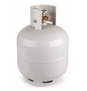
This author has investigated multiple cases where propane releases and flash fires were caused when the safeguards failed to function as they were intended.

The underlying hazards that create the need for the safeguards are:
1. Gas service valve. The user should be able to exercise control over the flow of propane to the appliance.
2. Pressure relief valve. The cylinder may be subjected to excessive internal pressure for either of two reasons: (a) if the cylinder is overfilled at room temperature and is later exposed to mildly higher temperatures (+25 degrees F or higher), the propane liquid can expand and create unsafe internal pressures; or (b) if the cylinder is filled to a safe level (i.e., approximately 20% vapor space above the liquid) and is later subjected to excessive heating from a fire, the liquid+vapor mixture can reach an unsafe pressure. In either case, the pressure relief valve’s job is to reduce the internal pressure by venting a small amount of the propane vapor until the internal pressure declines to a safer level. This safeguard helps prevent internal pressures that can cause the cylinder to rupture catastrophically.
3. Bleeder valve (+ dip tube). The bleeder valve and dip tube help the filling attendant visibly see when the liquid propane level in the cylinder has reached its maximum safe level (see 2 above). When the tiny stream of propane exiting the bleeder valve during filling changes from transparent vapor to a white mist, the maximum safe liquid level has been reached and the attendant is warned to stop the filling operation immediately.
4. Overfill protection device (OPD). The OPD is an automatically-actuated valve that is intended to achieve the same outcome as the bleeder valve (i.e., prevention of overfilling the cylinder with liquid), albeit without human intervention. The OPD comprises a toilet-tank style float inside the cylinder that closes off the flow path for liquid to enter the cylinder from the filling pump when the desired safe liquid level (see 2 above) has been reached.
5. Automatic shutoff valve. The Automatic shutoff valve (ASV) is a poppet-style valve that is intended to prevent the flow of propane vapor out of the cylinder until the connector nut has been fully tightened to a gas-tight sealing condition. In principle, an engagement tab inside the connector doesn’t engage the ASV’s spring-loaded isolation component until a satisfactory seal is made between the cylinder nozzle and the threaded connector nut. This is a feature that prevents gas flow out of the cylinder if the service valve is accidentally opened during storage or at any time before the appliance connection is made.
6. Excess flow valve. The Excess flow valve prevents or minimizes propane flow under circumstances where the connector is properly sealed but a downstream component (e.g., hose) fails in a way that fuel may be released to the environment instead of the appliance burner. The feature that carries out this function is a spring-loaded sphere that is normally positioned to permit a normal flow of propane vapor but is relocated to a position where the flow orifice is obstructed by the sphere when the drag force on the sphere exceeds the spring force (i.e., when flow velocity is high).

The subject safeguards (applicable to 20 lb propane cylinders) are described and specified in the CGA V-1 document “Standard for Compressed Gas Cylinder Valve Outlet and Inlet Connections”, specifically under connection style CGA 791.

While there is no doubt that the CGA 791 design has prevented numerous propane releases and injuries since it was first promulgated in 2000, this investigator believes it is inferior in one important way to the CGA 600 design that is currently approved only for small (1 lb) propane cylinders. The inferior feature involves the sealing geometry (radial versus axial) in the two designs, and the 791 design inherently provides a lower level of sealing certainty than the 600 design.

This investigator has opined that the 791 design’s inferior feature constitutes a safety defect if the resultant sealing inadequacy leads to a dangerous release of propane that causes personal injury or property damage.

The purpose of “Investigation Anecdotes” is to inform our readers about the intriguing field of engineering investigations. We hope you are instructed by this content, and we encourage you to contact us if you seek additional information.
 

Tire Failure Causes RV Fire

As farfetched as it sounds, this author investigated a Recreational Vehicle (RV) fire where the cause was tire failure. Consider these facts:

  • RV being operated on highway when right-front tire blew out.
  • Driver pulled over to right side of highway.
  • Witnesses photographed active fire at right-front corner of RV.
  • Fire damage to RV included near-complete melting of right-front aluminum wheel hub, with zero melting of the other five aluminum hubs.
  • Burn patterns on RV exterior indicated a low point of burning at right-front wheel well, and V-like patterns rising upward and spreading outward from there.

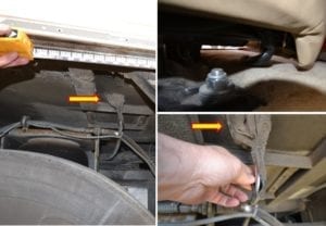
While the facts above are fully consistent with a fire origin at or near the right front wheel well, and no other origin location would be equally consistent, the evidence above fails to provide direct evidence of any fire causation mechanism. To discover the cause of the fire, our team found and inspected an exemplar RV of the same make and model and discovered an entirely new set of facts about the RV design – none of which survived the fire.  Consider the inset photo below and the following additional facts:

  • Several sources of combustible plastic and rubber were present inside the wheel well.
  • A set of four conductors (two of which were 10 AWG solid copper wire) inside a plastic wire loom was run through the wheel well.
  • The heavy-gauge wires provided power to the front passenger seat adjustment motor and were energized whenever the ignition key was in run or accessory mode.
  • The wire loom and wires were a few inches above the tire’s upper surface and a few inches inward from the tire’s inward edge.
  • When a rotating tire fails, elements of steel belting can partially disengage and whip around repeatedly at high speed, impacting softer materials within their reach.

Thus, after inspecting the exemplar, our team was able to supplement the burn pattern information with design information that confirmed a source of ignition (energized conductors with contemporaneously-damaged insulation) with several sources of fuel (plastic, rubber and plywood) in the area of origin.  Our causation scenario was the only hypothesis under consideration that was fully consistent with all of the facts – tire failure, followed by steel-belt whipping and damaging energized conductors, followed by ignition of nearby combustible plastics, followed by fire spread to right-front corner of RV structure.

The purpose of “Investigation Anecdotes” is to inform our readers about the intriguing field of engineering investigations.  We hope you are instructed by this content, and we encourage you to contact us if you seek additional information.


Statistical Inference and Product Failure Analysis

When a consumer product fails thermally, customers may get “steamed” and demand their money back.  When the failures are frequent enough that the Consumer Product Safety Commission receives dozens of complaints about “melted plastic” and “first degree burns” a few weeks after the initial launch of the product, they may require the seller to pull the offending product from retail shelves and issue a “safety recall” notice to all consumers.  If you consider a product that is being sold at a rate of 100,000 units per month, it is easy to see how quickly the recall costs could add up.

However, the matter could become even more problematic if the supply chain involves multiple entities (e.g. a product designer, a contract manufacturer, and a marketing entity).  When the recall costs are tallied up, the manufacturer and designer could find themselves in a legal battle to determine whether the thermal failures were caused by “design defects” or “manufacturing defects”.

One particularly challenging aspect of an engineering failure investigation is to understand why only a small percentage of all the shipped products fails prematurely.  By carefully examining the failed units, an engineer may be able to identify the correct failure mode(s), but inspection alone likely will not be sufficient to determine whether the root cause was a bad design or low quality manufacturing.

After the failure mechanism is identified (e.g., loose connection or excessive current draw) the engineer should examine and test a large number of “new-in-box” units to see if there is a correlation between parts that are “out-of-spec” and parts that fail when used normally.   If brand-new parts meet the dimensional and functional requirement of the design, it’s pretty obvious that the design wasn’t adequate to prevent the overheating.  On the other hand, a finding that many of the parts don’t conform to the design dimensions (and other requirements) doesn’t definitively prove that manufacturing defects were the cause of the safety problems.

In a recent investigation of a recalled consumer electronic product, this author discovered that 80% of “new-in-box” samples did not meet the design specification…but less than 3% of the samples failed thermally when first used.  Tellingly, we also found that 9% of the samples were not only “out-of-spec”, but “grossly-out-of-spec” and that each of the samples that failed thermally fell into the “grossly-out-of-spec” category.  (Conversely, none of the 20% of the “in-spec” parts failed when used normally, which provided validation that the design was adequate.)

Using “statistical inference” we concluded that it was virtually impossible (48 chances in a billion) for all of the failed samples to come from the “grossly-out-of-spec” population if only random forces were at play – hence there must be a “causal link” between the “grossly-out-of-spec” condition and the thermal overheating result.  Statistical methods proved extremely helpful in illustrating that the manufacturing “nonconformances” were indeed the “defects” that caused the safety recall!

The purpose of “Investigation Anecdotes” is to inform our readers about the intriguing field of engineering investigations.  We hope you are instructed by this content, and we encourage you to contact us if you seek additional information.